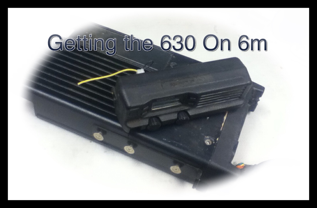
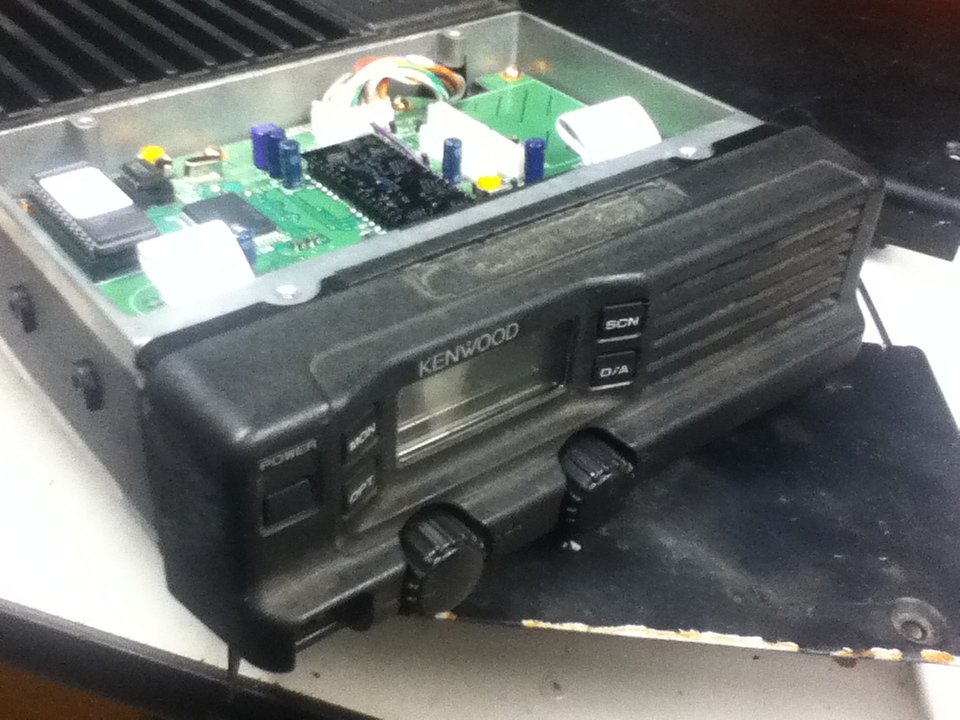
Look at the title picture… Control head with clipped yellow wire, clipped control cable. Radio unit with clipped control cable, no power cable. Big 15 pin Molex connector, no connections. This review is how to get this radio put together, up and operational.
While you can get replacement parts, in this tutorial, we are going to try and operate with parts on hand.
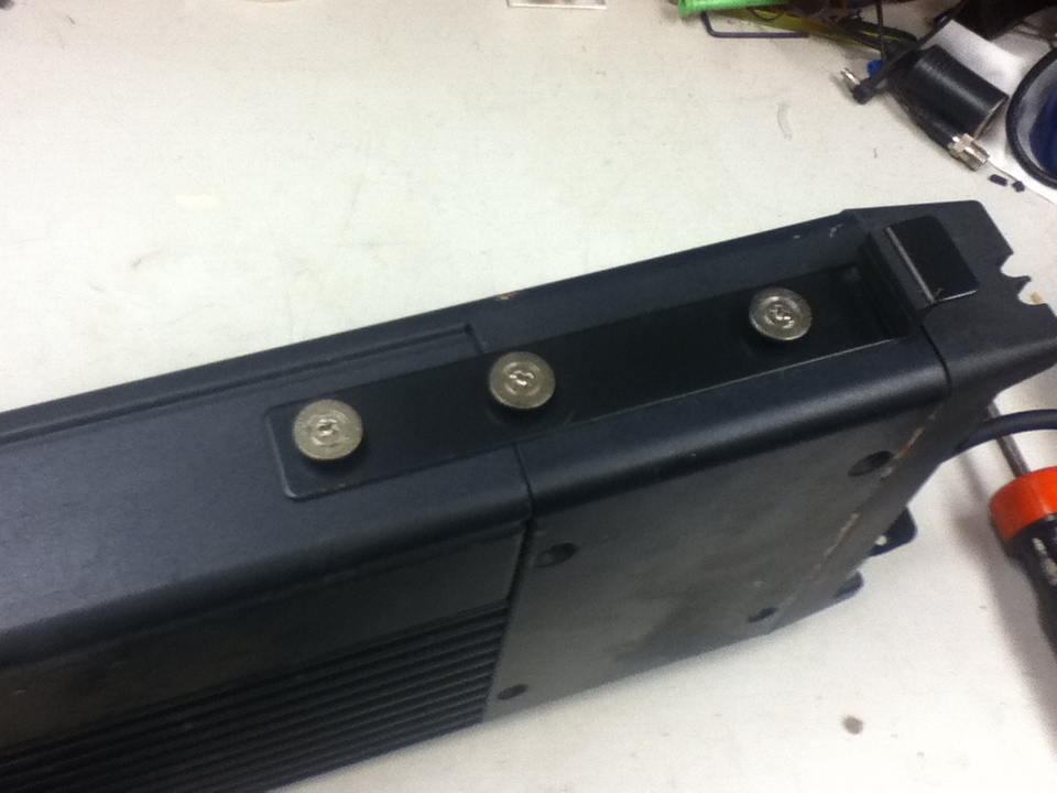
The first thing we need to do is get rid of the KRK-2 remote kit. This is the connector on the front of the radio unit, and the matching backside of the control head. In our case, the control cable has been cut and is useless.
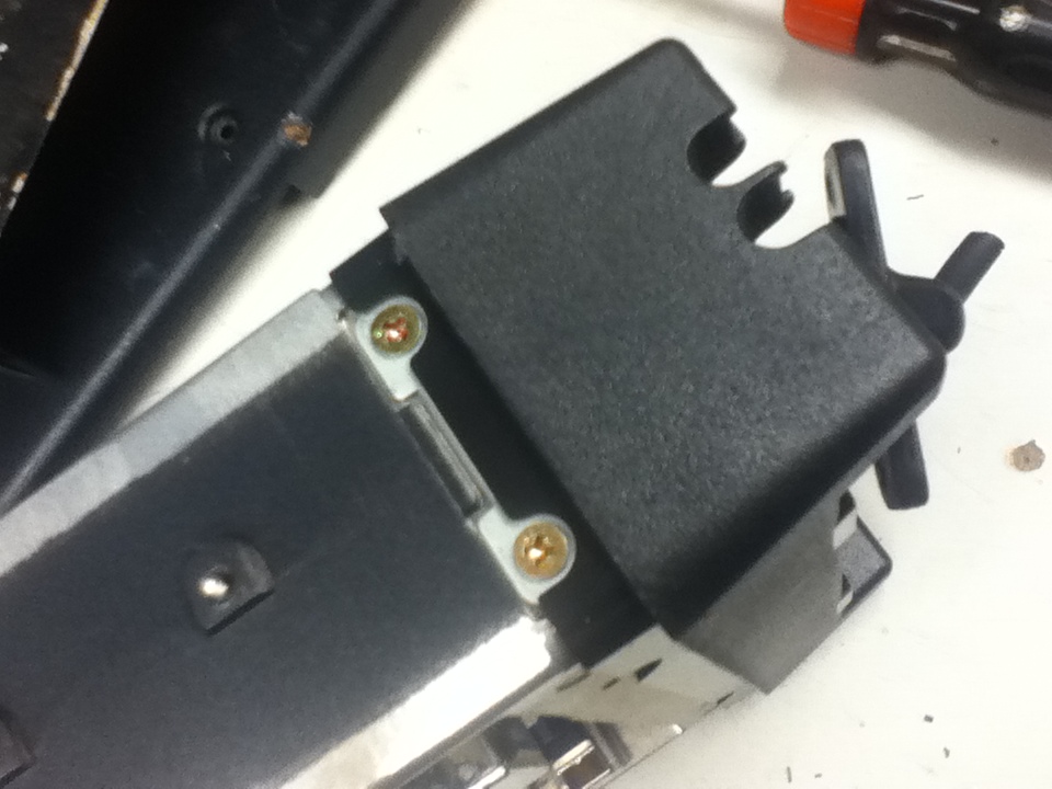
There are 2 countersunk screws on each side of the KRK-2 remote connector.
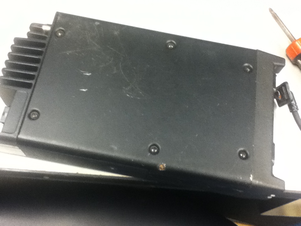
Bottom plate view. Notice the 6 screws to remove the bottom plate.
Remove the side rails from the radio unit. Both the top and bottom plates will have to be removed. 4 screws on the top plate, 6 on the bottom.
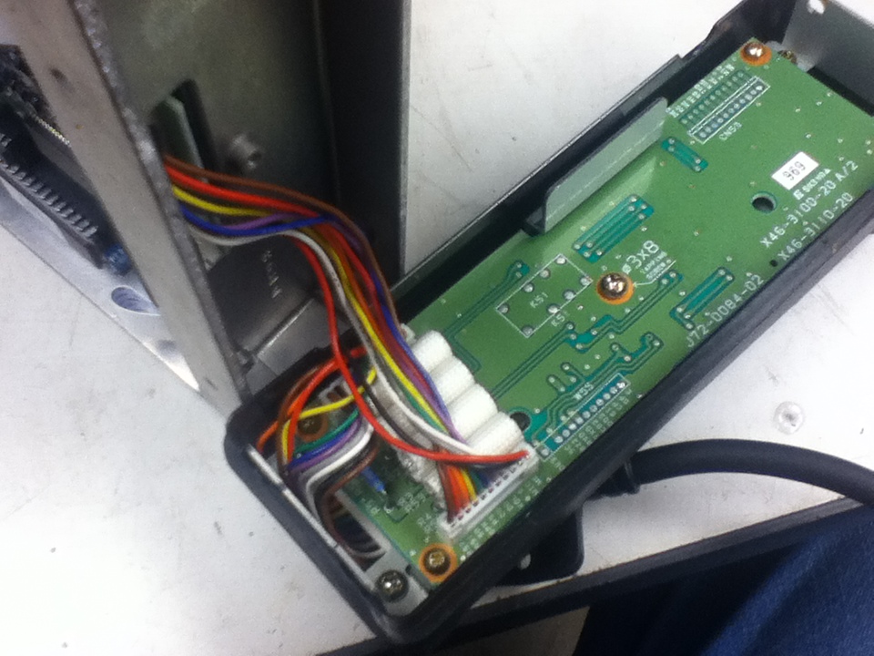
The KRK-2 remote plate is loose and connected by a single connector.
You will notice a similar procedure to remove the control head from the control head portion of the KRK-2 remote kit. You will be left with a control head which must be attached to the radio body.
Before we can attach the control head directly to the radio, we have some housekeeping to perform.
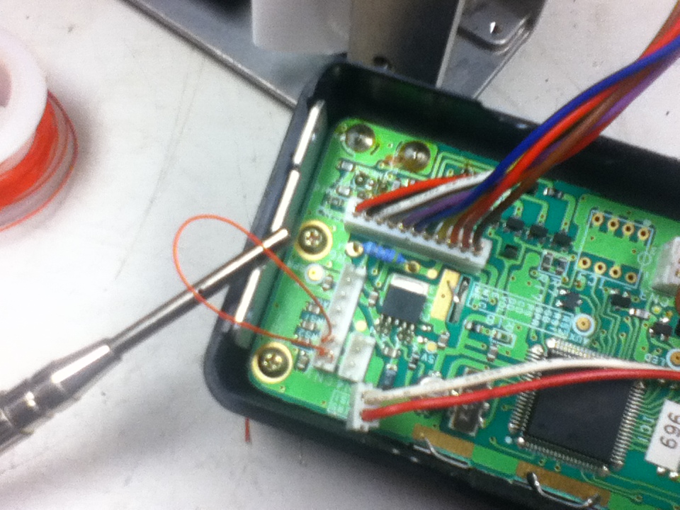
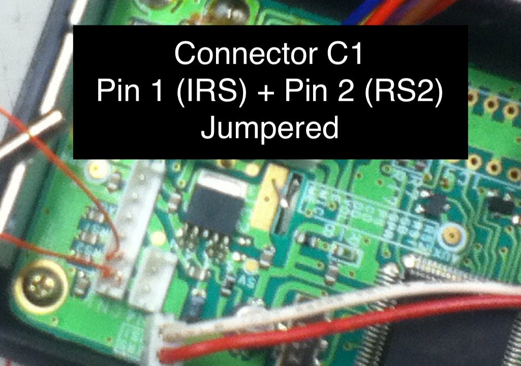
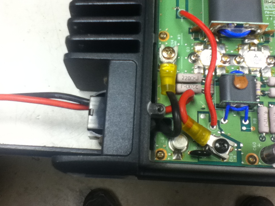
When you removed the KRK-2 connector from the head, we unplugged a cable. One of the pins that attached to the connector was actually a jumper that told the radio to use the internal speaker of the KCH-3 control head. Since the connector is now missing, we must jumper 2 pins on CN1 to again tell the radio to use the internal speaker. Pins 1 and 2 will accomplish this. I went “old school” and used wire wrapping technology, but you may choose to just blop a drop of solder, or use a clip, or similar.
That all being done you can attach the control head to the radio using the 4 countersunk screws.
The front control head now attached to the radio body.
It’s starting to take shape and look like a radio!
Now we have to figure out how to get power to the radio. There are various combinations of power cables that were available when the radio was in it’s heyday. They are getting increasingly difficult to find.
I can also tell you that many of the radios I have dealt with spent previous lives in trucks that spread salt and chemicals which have taken it’s toll on many of the connectors. I have opted to not use the connector and simply attach wires directly to the radio itself. I terminated the end with the ham standard “Anderson Powerpole” connection. I did not add a fuse to this connector at this time. The radio calls for a 20A fuse. In my industry, we fused both the POSITIVE (+) and the NEGATIVE (-) wires. I always thought this was over protective until I once saw a truck get it’s ground from the antenna connector when ground straps rotted of the chassis. I also have seen mistakes made where positive wires were connected to the ground and burned up an antenna wire (and the interior of a truck cab.) Fuses are good! They should be put in SOMEPLACE before the power supply.
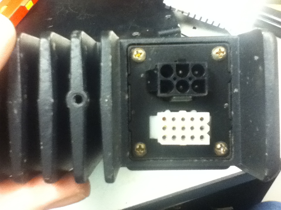
Here is the power connector on the rear of the radio. Below it is the 15 pin Molex connector. (More on that later…)
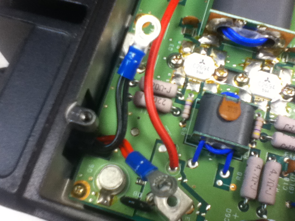
It takes some doing, but by drilling the empty holes of the power connector I was able to feed 2 10-12 gauge power wires through the connector. On the inside you will notice the POS and NEG power connections on the board attached by spade lugs.
Power connector and option (molex) plug.
With that step in place, you now have a radio that is ALMOST ready to power up.
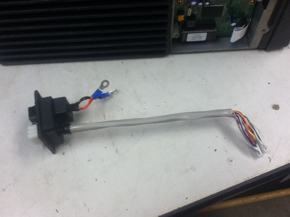
THE KCT-18 OPTION. (Ignition sense cable.)
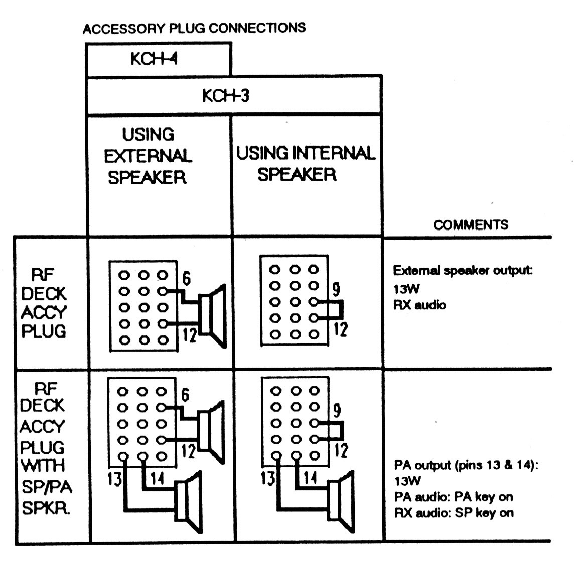
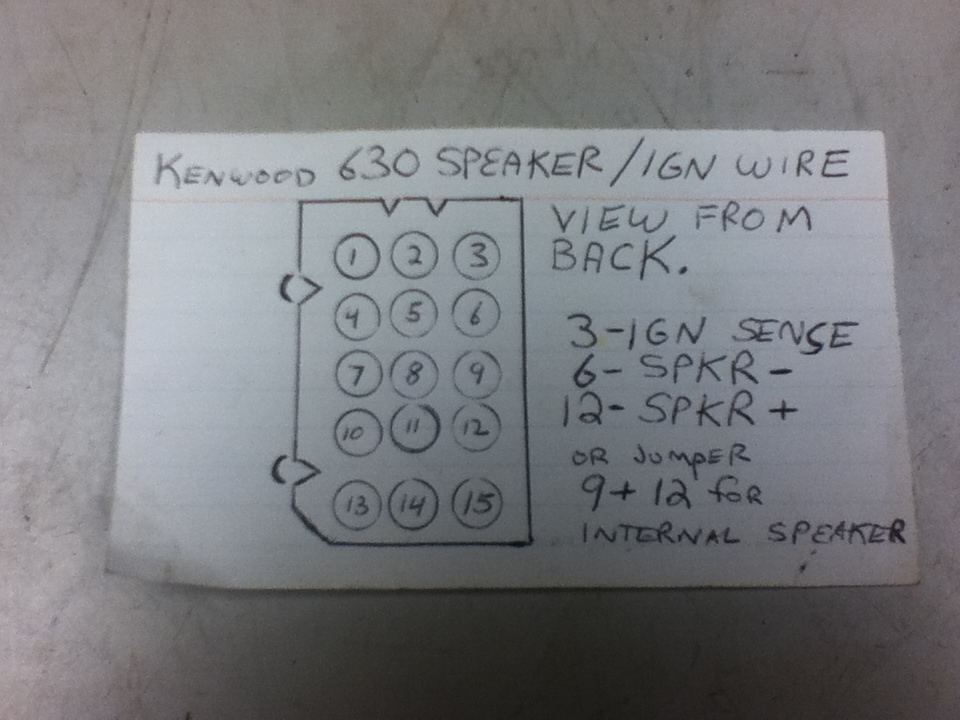
At this point we have to start deciding which options we wish to use with our radio. The accessory (option) connector on the rear of the radio may look daunting, but it is here that we can attach a speaker, an outside horn speaker, a PA speaker as well as pick of receive audio. (To a TNC or similar options.) In addition, with a jumper clipped inside the radio a wire can be attached on pin#3 of this option connector to turn the radio on and off with the vehicle. This jumper must be checked (W101). If it is OPEN, power will need to be applied to pin 1 to power the radio on. If it is shorted, power is not needed, and the radio will simply use the ON/OFF power button to turn the radio ON/OFF. (This is the way I have decided to use our example radio.)

We also have to decide at this point if we again wish to use the INTERNAL speaker, or an extension speaker. The KCH-3 control head includes an internal speaker. The full alphanumeric KCH-4 does NOT include a speaker, so one must be used.
Options.